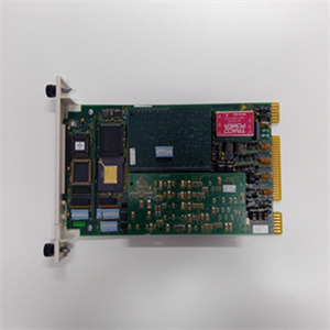
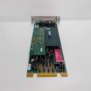
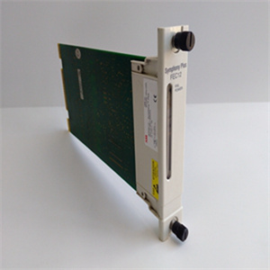
产品展示
联系我们
联系人:麦女士
手机:+86 15270269218
电话:
Q Q:3136378118
邮箱:stodcdcs@gmail.com
地址:江西省九江市瑞昌市东益路23号赛湖农商城401号
| 330180-50-05 |
注:除直接测量外
由监视器制作,许多通道类型提供
一种增强型数据集,由多种
取决于监视器的测量变量
类型及其配置。例如,径向
振动通道包括基本整体(直接)
振幅和间隙电压,1X
滤波振幅,1X滤波相位,2X滤波
振幅,2X滤波相位,非1X振幅,
和Smax。
提供了这些额外的测量变量
对于每个通道,警报报警设定点可以
根据需要确定每个变量。
危险报警设定点可建立在
从每个
频道
系列监视器模块
班长
类型
通道类型(脚注)数量
频道
(脚注)
/4000万
•径向振动
•轴向(推力)位置
•偏心率
•胀差(1)
四(2,3)
/4200万
与/40M相同,带有
以下附加通道
类型:
•加速度(4)
•速度(4)
•加速2(4)
•速度2(4)
•圆形验收区域(5)
•轴值
四(2,3)
/4400万
•空气衍生
•机场改造2
四
/45
•轴向(推力)位置
•胀差
•标准单坡道
胀差,胀差
•非标准单坡道
胀差,胀差
•双斜坡差速器
膨胀
•互补微分
膨胀
•案例扩展9
•阀门位置
四(3)
4600万
•液压径向振动(7)
•液压定子安装气隙
•液压加速
•水力推力
•水力速度
•定子端部绕组
•多模式功能
四(3)
/50米
•转子速度
•转子加速度
•零速度
•反向旋转
•转子加速度2
•零速度2
•反向旋转2
两(8,9)
/60 &
/61
•温度
•温差
六(10)
/62
•过程变量六(10、11)
/6400万
•动压四(12)
/7000万
•脉冲加速度
•加速2
•往复速度
•低频往复速度
四
/7200万
•往复式压缩机连杆
下降/杆位置/超高
压缩机
四(3)
/7700万
往复式压缩机
气缸压力,包括:
•吸入压力
•大压力
•小压力
•压缩比
•峰值杆压缩
•杆张力峰值
•杆反转程度
四
/82
电机定子绝缘监测器
•泄漏电流(每相)
•线路电压(每相)
•温度(高达3
频道)
九
零件号162096-01
修订版。H
6页共20页
监视器模块脚注
1、仅标准胀差
提供的功能。对于坡道差速器
扩展和补充输入
胀差,使用/45
改为定位监视器。
/42M提供单独的4至20 mA
每个通道的比例输出。这个
/40M不提供4至20 mA
输出。
3、监视器通道在
配对,多可执行其中两项
一次执行功能。通道1和2 can
执行一个功能,而通道3和4
执行其他(或相同)功能。
4、为速度或
加速度仅提供直接振幅。
为Velocity II或
加速度II提供1X振幅/相位
和2X振幅/相位和偏置电压
直接振幅的增加。
5、任何振动通道均可配置
传统的“饼状”接受区域
警报。为循环配置时
可接受区域,圆形(而非饼状)可接受区域警报
启用。参考/42M
操作/维护手册
其他信息,或联系
近的销售专业人员。
6、Case只能使用通道3和通道4
膨胀测量。
/46M提供频率响应
适用于机器的特性
转速非常慢,例如
水轮机/发电机组
以100 RPM或更低的速度运行。而且
特殊信号调节和跟踪
提供过滤,允许检测
负载区操作粗糙,剪切销故障,
以及其他特定水力条件。
/50M不适用于
超速保护应用。使用
3701/55紧急停机(ESD)系统,
相反
9、零速和反转
通道类型需要
/50模块,使其成为单通道
在这些配置中使用时进行监控。
/60和/61提供相同的
/60以外的功能不提供
4至20 mA比例输出。当这些
需要输出,使用/61。
/62设计用于接受静态
比例信号,如4至20 mA、1至5
Vdc或任何静态比例电压信号
介于–10和+10 Vdc之间。动态时
信号(即波形
信息是必需的),使用/40M
或/42M通常可编程为
自定义通道类型,使系统
几乎与任何静态或动态
来自压力、液位、温度、,
振动,流量


Note: In addition to the direct measurement made by the monitor, many channel types provide an enhanced data set consisting of a variety of measured variables that depend on the monitor type and its configuration. For example, radial vibration channels include the basic overall (direct) vibration amplitude as well as gap voltage, 1X filtered amplitude, 1X filtered phase, 2X filtered amplitude, 2X filtered phase, Not 1X amplitude, and Smax. These additional measured variables are provided for each channel, and ALERT alarm setpoints can be established on each variable, as needed. DANGER alarm setpoints can be established on any measured variable value returned from each channel. Series Monitor Modules Monitor Type Channel Types (footnotes) Number of Channels (footnotes) /40M • Radial Vibration • Axial (Thrust) Position • Eccentricity • Differential Expansion (1) Four(2, 3) /42M Same as /40M, with the following additional channel types: • Acceleration (4) • Velocity (4) • Acceleration2 (4) • Velocity2 (4) • Circular Acceptance Region (5) • Shaft Absolute Four(2, 3) /44M • Aeroderivative • Aeroderivative2 Four /45 • Axial (Thrust) Position • Differential Expansion • Standard Single Ramp Differential Expansion • Non-Standard Single Ramp Differential Expansion • Dual Ramp Differential Expansion • Complementary Differential Expansion • Case Expansion9 • Valve Position Four(3) 46M • Hydro Radial Vibration (7) • Hydro Stator-Mounted Air Gap • Hydro Acceleration • Hydro Thrust • Hydro Velocity • Stator End Winding • Multimode Functionality Four(3) /50M • Rotor Speed • Rotor Acceleration • Zero-Speed • Reverse Rotation • Rotor Acceleration2 • Zero Speed2 • Reverse Rotation2 Two (8, 9) /60 & /61 • Temperature • Differential Temperature Six (10) /62 • Process Variables Six (10, 11) /64M • Dynamic Pressure Four(12) /70M • Impulse Accel • Acceleration2 • Recip Velocity • Low Frequency Recip Velocity Four /72M • Reciprocating Compressor Rod Drop / Rod Position / Hyper compressor Four(3) /77M Reciprocating Compressor Cylinder Pressure, including: • Suction Pressure • Maximum Pressure • Minimum Pressure • Compression Ratio • Peak Rod Compression • Peak Rod Tension • Degree of Rod Reversal Four /82 Motor Stator Insulation Monitor • Leakage Current (each phase) • Line Voltage (each phase) • Temperature (up to three channels) Nine Part Number 162096-01 Rev. H Page 6 of 20 Monitor Module Footnotes 1. Only standard differential expansion capabilities provided. For ramp differential expansion and complementary input differential expansion, use the /45 Position Monitor, instead. 2. The /42M provides individual 4 to 20 mA proportional outputs for each channel. The /40M does NOT provide 4 to 20 mA outputs. 3. The monitor channels are programmed in pairs and can perform up to two of these functions at a time. Channels 1 and 2 can perform one function, while channels 3 and 4 perform another (or the same) function. 4. Channels configured for velocity or acceleration provide only direct amplitude. Channels configured for Velocity II or Acceleration II provide 1X amplitude/phase and 2X amplitude/phase and bias voltage in addition to direct amplitude. 5. Any vibration channel can be configured for conventional “pie-shaped” acceptance region alarms. When configured for circular acceptance regions, circular (rather than pieshaped) acceptance region alarms can be enabled. Refer to the /42M Operations/Maintenance Manual for additional information, or contact your nearest sales professional. 6. Only channels 3 and 4 can be used for Case Expansion measurements. 7. The /46M provides frequency response characteristics suitable for use on machines with very slow rotational speeds, such as hydraulic turbine/generator sets, which often operate at speeds of 100 RPM or lower. Also, special signal conditioning and tracking filtering is provided, allowing detection of rough load zone operation, shear pin failure, and other hydro-specific conditions. 8. The /50M is not intended for use in overspeed protection applications. Use the 3701/55 Emergency Shutdown (ESD) system, instead. 9. Both Zero Speed and Reverse Rotation channel types require both channels of the /50 module, making it a single-channel monitor when used in these configurations. 10. The /60 and /61 provide identical functions except the /60 does not provide 4 to 20 mA proportional outputs. When these outputs are required, use the /61. 11. The /62 is designed to accept static proportional signals such as 4 to 20 mA, 1 to 5 Vdc, or any static proportional voltage signal between –10 and +10 Vdc. When dynamic signals (i.e., those where waveform information is required) are used, a /40M or /42M can often be programmed as a custom channel type, making the system compatible with virtually any static or dynamic signal from pressure, level, temperature, vibration, flow, position, speed, or other transducers. Consult the factory or your local Bently Nevada sales professional for more information. 12. The /64M is primarily intended for monitoring combustor pressure pulsation instabilities (“humming”) in gas turbines. Note: Analog (4 to 20 mA) and digital (Modbus®) outputs from relay modules are intended for operator annunciation and trending purposes only, as they do not provide the fault tolerance or integrity necessary for highly reliable machinery shutdown purposes. For these applications, the /32M and /33 Relay Modules (described on the following page) should be used.
相关产品


