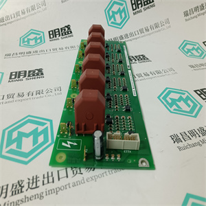
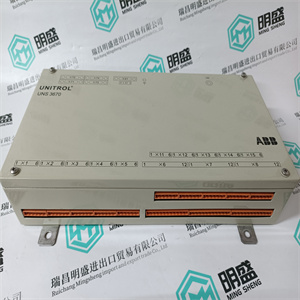
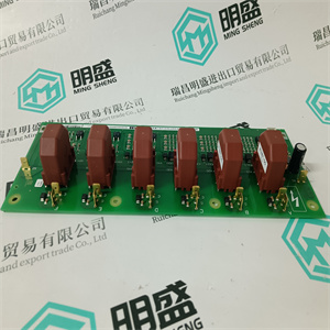
产品展示
联系我们
联系人:麦女士
手机:+86 15270269218
电话:
Q Q:3136378118
邮箱:stodcdcs@gmail.com
地址:江西省九江市瑞昌市东益路23号赛湖农商城401号
SDCS-FEP-1 该保护功能的应用领域是指所有可能过载的装置,通常过载值较低,但持续时间较长,这对设备和电缆的寿命是危险的。这些电流通常发生在声音电路中,线路过载(这种情况比实际故障更可能发生)。该保护的跳闸曲线(不能排除)由电流阈值I1和跳闸时间t1定义。更准确地说:•I1表示电流值,超过该值时,保护功能根据反时限跳闸特性命令断路器断开,其中时间-电流连接由关系式I2 t=常数(常数比通过能量)给出t1代表保护的跳闸时间,单位为秒,对应于I1的明确定义倍数,用于识别跳闸装置可用曲线中的定义曲线。要正确设置L阈值,必须知道负载(Ib)所需的电流,除以跳闸装置的In,并将设置值立即高于或等于获得的值:设置L=Ib I n设置L=Ib=85=0.85 I n 100此外,在电缆保护的情况下,应遵循以下关系Ib<I1<Iz,其中Iz是导线承载能力,I1是过载保护设置的电流值。示例:XT2N 160,跳闸装置类型Ekip LSI In=100,通过手动设置实现功能L(1 x In时I1=0.4,步骤0.02)。选择Ib=85A I1=0.86。通过手动设置,dip开关的位置应确保系数等于0.86;该系数乘以跳闸装置的额定电流得出所需的电流值。下图显示了获得所需倍增系数的dip开关的正确组合:I1=100 x(0.4*+0.02+0.04+0.08+0.32)=86A。过载电流的L函数跳闸时间根据所用曲线的类型而变化。关于示例中考虑的释放,可用曲线为4条,每条曲线的特征是通过一个特征倍数(3xI1)通过,不同的跳闸时间(t1=3s,12s,36s,60s)对应;由于这些是I2 t=const的曲线,因此可以在设置t1后识别不同于3xI1的倍数。作为具有I2 t常数的曲线,必须始终验证条件(3xI1)2 x t1=const=I2 t。


SDCS-FEP-1 The application field of this protection function refers to all the installations which can be subject to overloads - usually of low value but of long duration - which are dangerous for the life of apparatus and cables. These currents usually occur in a sound circuit, where the line results to be overloaded (this event is more likely than a real fault). The trip curve of this protection (which cannot be excluded) is defined by a current threshold I1 and by a trip time t1. More exactly : • I1 represents the current value beyond which the protection function commands the opening of the circuit-breaker according to an inverse time trip characteristic, where the time-current connection is given by the relation I 2 t = constant (constant specific let-through energy); • t1 represents the trip time of the protection, in seconds, corresponding to a well defined multiple of I1 and it is used to identify a defined curve among those made available by the trip unit.To set properly L threshold, it is necessary to know the current required by the load (Ib), divide it by the In of the trip unit and take the setting immediately higher than or equal to the value obtained : Setting L = I b I n Setting L = I b = 85 = 0.85 I n 100 Besides, in case of cable protection, the following relation shall be observed Ib < I1 < Iz where Iz is the conductor carrying capacity and I1 is the current value set for the overload protection. Example : XT2N 160, trip unit type Ekip LSI In=100, function L (I1=0.4 at 1 x In with step 0.02) through manual setting. Ib= 85A I1=0.86 is chosen. Through the manual setting, the dip-switches shall be positioned so that a coefficient equal to 0.86 is obtained; this coefficient multiplied by the rated current of the trip unit gives the required current value. The figure below shows the correct combination of dip-switches to obtain the required multiplying factor: I1= 100 x (0.4*+0.02+0.04+0.08+0,32) = 86A The trip time of L function for an overload current varies according to the type of curve used. As regards the release considered in the example, the available curves are 4 and each of them is characterized by the passage by a characteristic multiple (3xI1) to which a different trip time (t1=3s, 12s, 36s, 60s) corresponds; since these are curves with I2 t=const, it is possible to identify multiples different from 3xI1 after the setting of t1. Being a curve with I2 t constant, the condition (3xI1)2 x t1 =const =I2 t must be always verified.
相关产品


